WORKING SAFETY AT HEIGHT
Selecting, specifying, & managing mobile elevating work platforms (MEWP)
(a) Vertical ‘scissor’ lift
(b) Self-propelled boom
(c) Vehicle-mounted boom
(d) Trailer-mounted boom


**Photos arranged according to the list
SELECTION CRITERIA:
To decide which MEWP is suitable to be used, the followings should be taken into account:
• What work needs to be done***
• Who is going to operate the MEWP
• At what stage in the job will the MEWP be needed and what will the ground conditions are like at that stage; rough, prepared, poured slab, finished surface, etc.***
• What access is there to the site
• How much base area is available at the work position***
• what is the maximum ground bearing capacity at the work area and along the route to and from the work positions***
• How many people need to be lifted
• What height/outreached is required
• Will the MEWP be expected to move in the elevated position***
• Overhead power lines on site
• Are there any materials to be lifted and if so how heavy/long are they
• What wind loads can be expected***
***Priority
MANAGING THE RISK
Once a suitable MEWP is chosen, look at the hazards associated with using it, assess the risks and identify control measures to develop a safety working method.
Transport and delivery to site:
Think about what size of delivery vehicle or vehicle-mounted MEWP will need access to site or whether a self-propelled MEWP will have to be offloaded on the public highway:
• What time of day will be most appropriate and what additional measures will be required
• Will the MEWP need to be reversed off the carrier or, if vehicle-mounted, reversed onto site
• What size turning circle will be needed***
Storage/charging area:
• Keep MEWP in a secure compound or in a designated area with the engine or motor switched off
• The working platform lowered to its parking position and brakes applied
• The wheels should be chocked
Positioning before and during work:
• What is the ground bearing capacity at the work position and along the route to and from it
• Is there enough space for the outriggers to be deployed and what is the maximum point load (under a wheel, outrigger, or jack pad), are spreader plates required
• Will the MEWP have to operate on elevated floor slabs? Has the risk of the MEWP running off the edge of an elevated floor slab been considered?
Handling materials:
• If MEWPs are to be used directly to install materials, it is essential to know the weight and dimensions of those materials and to properly consider any manual handling and load distribution issues
• Boom-type MEWPs generally have smaller baskets and lower lift capacities than scissor-type MEWPs and their platform can ‘bounce’ at height due to the boom structure flexing. This usually makes them unsuitable to use for installing long or heavy materials, or bulky materials that may obstruct the function controls
• In these cases, consider using a scissor lift, crane or a telehandler of appropriate capacity in conjunction with an appropriate material handling attachment where necessary. This combination reduces the risk of overturning, removes the need to balance materials on the MEWP’s handrails and minimises the risk of injury due to manual handling
• If you plan the work properly the need for outreach may be avoided by, for example, preparing or reinstating the ground conditions in the area directly beneath planned overhead work or by adjusting the work schedule to delay the construction of low-level structures until work overhead has been completed
Hazards during use:
Look out for localised ground features, such as trenches, manholes and uncompacted backfill, which could lead to overturning? If operating on a pre-cast concrete slab, check the slab loading limits and how this compares with the maximum weight of the MEWP. Has enough time been allowed for the concrete to cure? What measures are in place to stop the MEWP running off the edge of the slab onto soft ground?
Think about wet, cold and windy weather:
• What is the manufacturer’s maximum wind speed in which the MEWP can operate safely
• How will the wind speed be checked (usually with an anemometer) and by whom
• Is the MEWP being operated between buildings where increased wind speed and/or turbulence can be a particular problem
On some MEWPs fitted with proportional controls there can be an element of ‘run-on’ when the controls are released. This is designed to create a smoother operation but can mean that the MEWP continues to move after the controls have been released. Therefore particular care must be taken when working close to overhead structures to avoid the risk crushing.
If there are overhead structures against which an operator could be trapped and then pushed onto the MEWP controls causing sustained involuntary operation of the platform, consider selecting a MEWP which has been designed to prevent such accidental contact with the controls. MEWPs with shrouded or otherwise protected controls are available.
Extra care must be taken if MEWPs are used to manoeuvre up through several levels of steelwork as there is a risk of the operator being trapped should the boom or basket strike the steelwork. This risk increases with the number of levels the MEWP operates through and if materials are loaded out onto the lower levels which can reduce clearance.
Look for any overhead hazards such as power lines, pipe bridges, arches or trees.
Think about how the MEWP interacts with other site traffic and personnel:
• Does the operator have limited visibility, particularly during reversing
• What is required in terms of vehicle route signage, pedestrian segregation barriers, cones, crossings etc
• Does any part of the MEWP protrude out of the confines of the site
• Are people below protected from the risk of falling objects
• When working in an area used by other workers or vehicles, the entire MEWP work area (based on reach distances and not just base structure footprint) should be barricaded using cones and warning signs etc.
Maintenance:
The trained operator is responsible for carrying out a basic daily/pre-use inspection and function check and records of these checks should be kept.
The operator should also be fully aware of the procedure you expect to be followed should they identify a fault with the MEWP, i.e. isolate the controls, tag the machine and report the defect to the person in control.
You should request a copy of the maintenance records as evidence that the MEWP and any related materials handling attachments that are going to be used on your site have been properly maintained.
Familiarisation:
Before being authorised to operate a particular make or model of MEWP, the operator should be familiarised with it by a competent person. Familiarisation should follow on from basic training and should cover:
• manufacturer’s warnings and safety instructions
• the control functions specific to the particular MEWP
• the function of each safety device specific to the particular MEWP
• operating limitations such as limiting wind speed, wheel and outrigger loadings, set up requirements, maximum operating slope etc.
• emergency lowering procedures
• safe working loads or load charts
• the maximum number of people who can be carried
• the maximum safe operating speed
** All of the above can be found in the information supplied with the machine
On completion of their familiarisation, the operator should know whether or not that particular MEWP is designed for the operator to travel on with the work platform in the elevated position and whether or not the controls are protected to prevent accidental contact with the operator’s torso.
It is important that you allow enough time for your operator to check, inspect, function test and familiarise themself with every new MEWP.
All familiarisations should be recorded.
Personal protective equipment (PPE):
One of the biggest risks in using boom-type platforms is being thrown out of the basket if the boom swings, jolts or tilts away from the machine’s centre of gravity, or if the operator overreaches (usually by standing on the guard rails).
A hard hat with chinstrap and cold/wet weather high visibility clothing should also be worn.
Emergency and rescue procedure:
The emergency and rescue plan should identify trained, site-based personnel who would be available to lower the work platform using the control panel or emergency descent system situated at ground level. These people should be included in the familiarisation training for the specific machines being used on site.
The plan should also include the call-out details for the service engineer or other person who is competent and authorised to lower the work platform in the event of an emergency.
Job Documentation:
The next stage is to record the planning and communicate it to all those involved with the work.
Before work starts the plan should be reviewed to allow for any changes in circumstances, such as changes in site access, ground conditions, the task to be carried out, the weather conditions etc.
Make a record of who has been briefed and issued with the plan.
Tell those involved in the work to report any problems with the plan immediately. Should they need to deviate from the plan, this should be agreed with the competent person before any changes are made.
General inspections
Requirement
1. When a building is being constructed or demolished at a height greater than 75 feet (22.86 m), verify that at least one elevator or personal hoist with an emergency communication system is in place.
2. When a personal hoist requires a jump, verify that all necessary permits are obtained and testing performed.
3. When a building is being constructed or demolished at a height greater than 75 feet (22.86 m), verify that a standpipe system is available and in redlines at all times for use by the Fire Department.
(i) Verify that values are in place at each story below the construction floor.
(ii) Verify that standpipes are connected to a water source and Siamese connection.
(iii) Verify that Siamese hose connections are free from obstruction and are marked by a red light and a sign reading, “Standpipe Siamese Connection.”
(iv) Verify that no breach exists by visually tracing standpipes risers, cross connections and Siamese connections.
4. If a construction shed is located within 30 feet (9.144 m) of the building, verify that the construction shed is constructed of noncombustible materials.
5. Verify that interior and exterior guardrails and toe boards are provided and properly installed to meet the standards described in section 3307.8 of the building code.
6. Verify that all stairwells have standard handrails.
7. Verify that all signs required by section 3301.9 of the building code are installed and contain the required information.
Safety netting inspections
Requirement
1. Verify that horizontal safety netting is maintained not more than two stories below the stripping operation floor on concrete structures or the uppermost finished and walk able concrete floor is more than six stories or 75 feet (22.86 m) in height above the adjoining ground or adjoining roof level, whichever is applicable.
2. Verify that horizontal safety netting projects outward horizontal from the edge of the floor a minimum of 10 feet (3.048 m).
3. Verify that omitted horizontally safety netting in designated crane and derrick lifting areas is indicated and approved on the crane application and the site safety plan.
4. For steel frame construction, where the steel frame extends more than eight stories above the walk able concrete floor, verify that the vertical safety netting is provided on the floors at and below the topmost working metal deck where this deck is substantially completed and that the required guardrails and toe boards are in place.
5. Verify that vertical safety netting is provided on all floors below the floor on which horizontal netting is required.
6. Verify that vertical safety netting is secured and kept closed at all times, except during actual loading operations or perimeter construction operations.
Maintenance of site and adjacent area inspections.
Requirement
1. Verify that all areas used by the public are maintained free from ice, snow, grease, debris, equipment, materials, projections, tools, or other items, substance, or conditions that may constitute a slipping, tripping or other hazard.
2. Verify that guards, shields or barricades surround all exposed, electrically charged, moving or otherwise dangerous parts of machines and construction equipment so as to prevent contact with the public.
3. Verify that there are no exposed hose lines, wire, rope, or other items that may constitute a tripping hazard to the public.
4. Verify that adjoining property is protected when the height of the building exceeds that of the adjoining property.
5. When the building is extended, enlarged or increased in height so that any portion of such building, except chimneys or vents, extends higher than the top of any previously constructed chimneys within 100 feet (30.48 m).
Housekeeping inspections
Requirement
1. Verify that floors and stairs are clean from excess debris.
2. Verify that tools and equipment not in use are kept away from edges or openings.
3. Verify that the roof of the side walk shed and the street are free of debris.
4. Verify that sufficient containers for the storage of garbage and debris are provided.
5. Verify that containers are covered and secured when full.
Removal and storage of material inspections
Requirement
1. Verify that combustible waste material and combustible debris have been removed from the site.
2. Verify that material stored on floors of a building is secured when not being used.
3. When exterior walls are not in place, verify that stored material is kept at least 10 feet (3.048 m) back from the perimeter of the building, or at least 5 feet (1524 mm) back area is less than 1,000 square feet (304.8 m), or at least 2 feet (609.6 mm) back from the perimeter of the building on upper working floors located not more than two stories below the stripping operation on concrete floor on steel structures.
4. Verify that no material hangs over the edge of a building unless banded and braced for relocation by the end of the workday, except on the floor of the stripping operation and on floors designated as the lumber or steel mill.
(i) On floor of the stripping operation, verify that material that overhangs the floor is banded and braced, overhangs by not more than one-third of its length, and is relocated by next workday for concrete operations.
(ii) Where the steel mill and lumber mill are located, verify that any material that overhangs is relocated by the next workday.
Protection of sidewalk inspections
Requirement
1. Verify that valid permits for sidewalk sheds have been obtained, have not expired, and are posted in central, visible area.
2. Verify that approved drawings of the sidewalk shed are at the construction site.
3. Verify that sidewalk sheds extend the entire perimeter of the building.
4. Verify that when the building exceeds 100 feet (30.48 m) in height, the sidewalk sheds extend 20 feet (6.096 m) beyond the property line.
5. Verify that required sidewalk sheds remain in place until the structure is enclosed, all exterior work completed, the sash is gazed above the second story, the exterior façade is cleaned down, all outside handling of material equipment and machinery is completed, and dismantling of a hoist, crane, or the use of a derrick in their removal above the second story has been completed.
6. Verify that all openings in sidewalk sheds, fences and railings for loading purposes are kept closed, barricaded, protected, or guarded at all times.
7. Verify that sidewalk sheds are illuminated at night by the equivalent of 100-watt bulbs spaced 15 feet (4.572 m) apart at a minimum height of 8 feet (2.44 m) above the sidewalk.
8. Verify that temporary footbridges and walkways for the public are at least 5 feet (1.524 m) in width.
Warning signs and lights inspections
Requirement
1. Verify that all areas that are dangerous or hazardous to the public or areas where work is performed to the public or areas where work is performed near vehicular traffic are appropriately marked with warning signs and lights.
2. Verify that steps necessary to protect the public are taken, including provisions for flagmen/flag women whenever intermittent operations are conducted on or across areas open to the public or when dangerous operations, such as blasting, may affect such areas.
Scaffolds, structural ramps, runways and platform inspections
Requirement
1. Verify that where they pose a risk to the public that all structural ramps, scaffolds, runways and platforms are provided with guardrails, toe boards, screening, or nets, unless otherwise specified by the building code.
Material handling and hoisting equipment inspections
Requirement
1. Verify that all certificates of approval, operation, and onsite inspection for all cranes, derricks, and cableways have been obtained and are available for inspection at construction site.
2. Verify that all permits for highway and street closing are available for inspection at construction site.
3. Verify that licenses of crane operators are available at the construction site.
4. When a crane is to be jumped, verify that it is in accordance with the schedule submitted by the professional engineer and approved by the department.
5. Verify that a means of communication exists between the responsible parties when the operator of hoisting machinery has no vision of the lift or loading areas.
6. Verify that a program has been established and is operational for the control of pedestrian and vehicular traffic around the construction site during all lifting and hoisting operations.
7. Verify that flagman/women are present to stop pedestrian and vehicular traffic during the following intermittent operations:
(i) During all lifting and hoisting operations;
(ii) When trucks enter and exit the site;
(iii) When dangerous operations e.g. blasting, occur;
(iv) When the sidewalk and street is temporarily closed.
1.0 INTRODUCTION
1.1 BACKGROUND OF STUDY
Malaysia is a developing country which is located in South-East Asia. The demands for buildings, for commercial or residential use, are high especially in Kuala Lumpur, the capital city of Malaysia. A building is designed to support the load applied to it safely. The ability of a building to sustain the applied loads depends on the building's foundation system. Foundation is an important part of every building, which interfaces the superstructures to the adjacent soil or rock below it. The superstructure loads will be transferred to the underlying soil or rock. Without a proper design and construction of foundation, problems such as cracking, settlement of building may occur and even to the extent, the whole building may collapse within its design life. Therefore, a proper foundation system is required to maintain the safeness of a building. It is because defects are concerned by society at large due to their possible dangers such as structural collapse and loss of use. The use of modern building construction techniques and developments in material technology may be viewed as improvements to a building. Some historic buildings in Malaysia, as in the case, in Batu Pahat district, are at risk from defects because these buildings are not being well cared for, due to lack of knowledge and high cost of repair and maintenance. Basically, it is very important to recognize and diagnose the defects at each building element in historic buildings because there are so many defects that occur at various locations with different types of causes and symptoms. In majority of historic buildings in Malaysia, the existing structures are normally made from stone, brickwork, plaster and timber.
According to the National Building Agency (1985), defects occur either because of poor design, or low quality workmanship, or because the building was not constructed according to the design, or because it has been subject to factors not allowed for in the design. These primary causes may operate singly or in combination and result in defects indicated by changes in composition of materials; in the construction itself; in the size, shape or weight of materials; or simply in appearances. ) there are five main factors that govern building defects or problem to historic buildings which will be discussed in the later sections.
1.2 STATEMENT OF PROBLEM
Defects on buildings can occur on any part of the building such as roofing and column matter, cracking of wall and slab, whereas during construction period, which the foundation might have defects. It is more common to observe building defects on historical/old buildings. As discussed before, by according to the National Building Agency (1985), defects occur either because of poor design, or low quality workmanship, or because the building was not constructed according to the design, or because it has been subject to factors not allowed for in the design. These primary causes may operate singly or in combination and result in defects indicated by changes in composition of materials; in the construction itself; in the size, shape or weight of materials; or simply in appearances. In the care and conservation of historic buildings in Malaysia, the understanding of the nature of the building materials and accurate diagnosis of defects is most important. This is because historic buildings are like older people, vulnerable to all sorts of diseases. Therefore, in order to chase this problem, conservators, architects, engineers, builders, building surveyors, contractors and those involve in building conservation should first become familiar with the building materials in common use before going deeper into the proper techniques to repair and maintenance in historic buildings, structures and monuments. It is important to be able not only to diagnose simple defects and instruct repairs, but also to recognize and describe those problems which need expert help and act accordingly. There are five possible factors that might lead to building defects, which are;
(a) Climatic Conditions
Like many other tropical countries, Malaysia has heavily rainfall and warm sunshine all year round. This implies that buildings in the country tend to weather rapidly, particularly in respect to external building materials which are exposed to external causes such as rain, wind, solar radiation and atmospheric pollution.
(b) Locations of Building
Historic buildings that are located near the sea or rivers tend to have common building defects. This is because the water coming from the ground causes dampness penetration and structural instability. In addition, solutable salt which comes from the sea and together with the presence of a polluted atmosphere can cause damage to the exterior surface of the buildings.
(c) Building Type and Change of Use
Most historic buildings that maintain their original functions or uses appear to have fewer problems compared to buildings that change their use and function. This is because historic buildings were built to only hold certain loads and sometimes may not withstand additional loads on the existing structure.
(d) Maintenance Approach to the Building
Building maintenance organized through a rigorous of cyclical maintenance plays a major role in preventing building defects. Historic buildings that neglect building maintenance may fall into several defects which may lead to structural failures. To secure the general structural stability, it is important to regularly inspect not only the main structural elements like roof structure, beams and columns but also other common building parts.
(e) Building Age
Basically all elements of historical buildings tend to deteriorate at a lesser or greater rate depending upon their location and function. Aging building materials, particularly timber should be checked frequently. The proper treatment of building repair and maintenance should be given full considerations.
One of the advantages of building with structural concrete is its reparability. Proper repair techniques and materials are important to taking advantage of that attribute. But the key to successful concrete repair lies in understanding why it became necessary, then being sure to address the root cause of the problem.
1.3 OBJECTIVES OF STUDY
Building defects usually do occur in older or historical buildings. This research project is being carried out by making a field trip around Batu Pahat district area. This project is mainly involving discussions on the building defects found in the Batu Pahat area. These cases are about finding the information of factors that lead to building defects, and also getting possible solutions on how to prevent or repair the defects. On the other hand, a study case trip on the defects of building foundations and scaffoldings is planned as well, which is held in a construction site in, Taman Wira, Parit Raja. These are the parts of buildings which comprise the content in this project report;
(a) Building foundation
(b) Slab
(c) Column
(d) Wall
(e) Roofing
(f) Formwork
(g) Construction joint
(h) Scaffolding
(i) Types of machinery and their operation
Conclusions are drawn from the case studies conducted.
1.4 SIGNIFICANCE OF THE STUDY
The purpose of this research project on the building defects is to expose the students on the possibilities and factors that might lead to defects on buildings. From this exposure, students will be able to find the possible suggestions on prolonging the effects of maintenance to the particular building. Besides, through the case studies conducted in the district of Batu Pahat, five possible factors that lead to building defects have been thought of;
(a) Climatic Conditions
Like many other tropical countries, Malaysia has heavily rainfall and warm sunshine all year round. This implies that buildings in the country tend to weather rapidly, particularly in respect to external building materials which are exposed to external causes such as rain, wind, solar radiation and atmospheric pollution.
(b) Locations of Building
Historic buildings that are located near the sea or rivers tend to have common building defects. This is because the water coming from the ground causes dampness penetration and structural instability. In addition, solutable salt which comes from the sea and together with the presence of a polluted atmosphere can cause damage to the exterior surface of the buildings.
(c) Building Type and Change of Use
Most historic buildings that maintain their original functions or uses appear to have fewer problems compared to buildings that change their use and function. This is because historic buildings were built to only hold certain loads and sometimes may not withstand additional loads on the existing structure.
(d) Maintenance Approach to the Building
Building maintenance organized through a rigorous of cyclical maintenance plays a major role in preventing building defects. Historic buildings that neglect building maintenance may fall into several defects which may lead to structural failures. To secure the general structural stability, it is important to regularly inspect not only the main structural elements like roof structure, beams and columns but also other common building parts.
(e) Building Age
Basically all elements of historical buildings tend to deteriorate at a lesser or greater rate depending upon their location and function. Aging building materials, particularly timber should be checked frequently. The proper treatment of building repair and maintenance should be given full considerations.
1.5 LIMITATION OF THE STUDY
For this research project on the defects of building, the study has been limited in the district of Batu Pahat, specifically, in the older part of town in Batu Pahat, a construction site in Batu Pahat area, and a housing construction site in Taman Waja, Parit Raja. Pictures on the defects were taken as a proof of case study. Safety helmets and boots were used as a protective equipment during the site investigation. The research was done on the 12th of February 2009.
1.6 DEFINITION OF TERMS / TERMS OF REFERENCE
PPE – An abbreviation for Personal Protective Equipment. PPE is a set of safety/protective equipment used when a person is in the construction site. PPE includes safety helmet, safety boots, goggles, etc.
Formwork – A mould or a box which wet concrete can be poured in it and to contain the placed concrete, mould it to the required dimensions and remain in place till finally it has harden.
Scaffolding – a temporary framework used to support people and material in the construction or repair of buildings and other large structures.
1.7 METHODOLOGY
The main procedure used/planned during this case study is by taking pictures on the defects of buildings. Extra information is collected by doing a simple interview with a site engineer on duty regarding on uncertain defects on workplace. The methodology is summarized into the flowchart below:
***Based on your group's work programme
2.0 FINDINGS & DISCUSSIONS
In this section, the findings on the building defects are summarized in this section including pictures.
2.1 BUILDING FOUNDATION

A whole building may, to the extent, collapse due to the failures in its foundation system. Therefore, it is important to identify the factors that can cause a foundation system to fail and also the ways to minimize these problems. The major cause for foundation failures especially in expansive soil is due to water, just like the type of soil that Batu Pahat area has.
Possible factors:
- Soil Moisture – Soil moisture is loss through 3 processes that are evaporation, transpiration and combination of both. Evaporation losses can be noticed by the appearance of cracks on the walls. The foundation will move up and down during each cycle and the length of foundation will be shorter during wet cycle. The transpiration loss is limited on top shallow soil. The estimation of transpiration loss is difficult because transpiration depends on the type, size and density of plant and also the ambient wind and temperature.
- The major problem the plants pose to a foundation is the existence of surface roots beneath a shallow foundation. As the root grows, the shallow beam will be jacked upward. Besides that, removing old trees near to a foundation may also causes problem as the decaying roots can results in upheaval and voids which will later resulted in settlement. On the other hand, tree roots can enhance the stability of foundation by increasing the soil resistance to shear.
- Lateral movement can occur during soil erosion, sliding or sloughing. The soil movement can cause water to sip into the soil, reducing the cohesion and structural strength of the foundation.
- Settlement is another problem deals with foundation. Settlement occurs as a result of consolidation or compaction of fill, base or sub-base materials.
- The failure of a deep foundation may also due to the failure of its pile cap. The failure movement can be seen in Figure below.

Suggestions on preventing/maintenance:
These are some of the possible suggested solutions to prevent the cases above from occurring:
- The presence of trees near the building will exacerbate shrinkage in clay soils as the tree sucks moisture out of the ground. Trees can be a major contributor to shrinkage in reactive soils. Options include installation of cut off walls for root control with appropriate root pruning (an arborist’s advice is required to ensure tree health and stability is maintained) or removal of trees within the influence zone of the footings. The influence zone will vary with tree size and type, soil type and landform, consequently an arborist’s advice and possibly trial excavation to determine extent of roots is necessary. Works to trees generally require Council approval.
- Moisture control to the building perimeter – This is a strategy whereby the changes in moisture content below the footings are minimised by appropriate site grading, drainage and moisture control devices. The purpose of moisture control devices is to maintain stable water content in the soil below the footings by creating an increased path length for evaporation to the surface. Typical systems include:
Ø paving to the perimeter of the building;
Ø cut off walls to the perimeter of the building;
Ø buried impermeable membranes around the building;
Ø a combination of the above.
2.2 SLAB
 This picture is taken outside an old shophouse in BP.
This picture is taken outside of GDS Ford Leather. From the picture above, it can be seen that the tiles on the slab show cracking. This is due to the concrete slab below the tiles have been settled down. There are a few factors that might lead to the defect of the slab shown above.
Possible factors:
- Ground water sources and when the floor slab is in contact with saturated ground, or if drainage is poor. Moisture moves to the slab surface by capillary action or wicking. Factors affecting this include depth of the water table and fineness of soil below the slab. Fine grained soil (Batu Pahat area comprises of soft soils) promotes moisture movements from considerable depths compared to coarser sub grade material.
· Water vapour from damp soil will diffuse and condense on a concrete slab surface that is cooler and at a lower relative humidity due to a vapour pressure gradient.
· Residual moisture in the slab from the original concrete mixing water will move towards the surface. It may take anywhere from six weeks to one year or longer for a concrete slab to dry to an acceptable level under normal condition. Factors that affect the drying rate include the original water content of the concrete, type of curing, and the relative humidity and temperature of the ambient air during the drying period. This is the only source of moisture in elevated slabs. Any wetting of the slab after final curing will elevate moisture levels within the slab and lengthen the drying period.
- Vibration from nearby traffic roads due to the heavy transportation.
Suggestions on preventing/maintenance:
Avoiding problems associated with high moisture content in concrete can be accomplished by the following means:
· Protect against ingress of water under hydrostatic pressure by ensuring that proper drainage away from the slab is part of the design.
· Use a 6 to 8 inch [150 to 200 mm] layer of coarse gravel or crushed stone as a capillary break in locations with fine-grained soil sub grades.
· Use a concrete mixture with a moderately low water cementitious material (w/cm) ratio (about 0.50). This reduces the amount of residual moisture in the slab, will require a shorter drying period, and result in a lower permeability to vapour transmission. Water reducing admixtures can be used to obtain adequate workability and maintain a low water content. The water tightness of concrete can be improved by using fly ash or slag in the concrete mixture.
· Curing is an important step in achieving excellent hardened concrete properties. However, moist curing will increase drying time. As a compromise, curing the concrete under plastic sheeting for 3 days is recommended and moist curing times greater than 7 days must be avoided. Avoid using curing compounds on floors where coverings or coatings will be installed.
· Allow sufficient time for moisture in the slab to dry naturally while the floor is under a roof and protected from the elements. Avoid maintenance and cleaning operations that will wet the concrete floor. Use heat and dehumidifiers to accelerate drying. Since moisture transmission is affected by temperature and humidity, maintain the actual service conditions for a long enough period prior to installing the floor covering.
2.3 COLUMN

A column in structural engineering is a vertical structural element that transmits, through compression, the weight of the structure above to other structural elements below. For the purpose of wind or earthquake engineering, columns may be designed to resist lateral forces. Other compression members are often termed "columns" because of the similar stress conditions. Columns are frequently used to support beams or arches on which the upper parts of walls or ceilings rest. From the photo above, notice that the crack occurred at the column of the building, which might be caused of the excessive loading that has been transferred from the beam to the column. Specifically, this failure is due to excessive shear force by the beam.
Possible factors:
If the column load is gradually increased, a condition is reached in which the straight form of equilibrium becomes so-called neutral equilibrium, and a small lateral force will produce a deflection that does not disappear and the column remains in this slightly bent form when the lateral force is removed. The load at which neutral equilibrium of a column is reached is called the critical or buckling load. The state of instability is reached when a slight increase of the column load causes uncontrollably growing lateral deflections leading to complete collapse, but from the case taken, as seen in the picture, the column still has the strength to support the load of the superstructure.
These are the possible factors that caused the cracking on the column:
- Failure to follow engineered plan and specifications and/or not providing required documentation. This might cause the column’s durability to be lower.
- Shear or flexural failure of the column.
- The quality of the reinforced steel is not up to standard as this would lower the ability of load-bearing of the column.
- The quality of concrete might be poor. Possibly, the amount of the cement is not adequate. Therefore, it is necessary to make severe quality controls in the construction site; the water-cement ratio, arrangement of reinforcing bars and so on.
Suggestions on preventing/maintenance:
These are some useful recommendations that could solve the failure of the column, especially due to shear or flexural failure:
- It is necessary that larger size of columns should be employed in order to prevent floor/slab from falling down, not neglecting the total cost of the project.
- Multi-storey buildings with retail store in the first storey should be designed under consideration of eccentricity between centres of gravity and rigidity.
- Shear reinforcing bars should be placed in the beam-to-column joints to prevent brittle failure in beam-column joints (referring from the case photo above on “Column”).
- Number of shear reinforcing bars should be increased in the vicinity of column ends because in these areas, stresses such as bending moment and shear stress become large.
Strong columns are needed to provide strength to withstand the loads from a superstructure. This section stresses on how a better quality column is made:
(a) All reinforced concrete columns should be made in one piece before the wall is built and hoisted. They should not be made piece by piece as this would not provide ample space for the ties with walls when the walls are built. They should contain bars for wall ties and ring beams when constructed.
(b) Column reinforcement should be made up of 4 vertical bars with hoops holding them together, spaced at approximately the same as the width of the column. Bars should be anchored in the foundation.
(c) End of the steel hoop should be bent 135º towards the centre of the column. This application is useful for earthquake resistance. During earthquake, the structure will maintain stable and would not cause deadly failure to parts of building and collapse on the spot.
(d) Column steel must be covered with a minimum of 2cm of concrete all around. The column steel which is not properly covered would cause the formwork for the concrete against the steel in column, and when cement was poured, the steel will not be remained at its origin position (All component of superstructure will collapse when under stress due to the column failure).
(e) Steel reinforcement of the column should not be exposed to open air. Chemical process will seep in between steel reinforcement and water and air will “contaminate” the column. Corrosion happens on steel due to chemical content in water and the atmosphere around the column.
(f) When doing mix concrete, ensure that only clean water is used, as the water taken from the river, drain, etc, which contain salt or chemical that will reduce the concrete strength of the column. Reduce the amount of gravel if the sand contains stones and ensure that the ratio of water and cement and sand used is at its proper ratio. Over-contented of water will produce weaker column.
2.4 WALL

This picture above is the example of a defect on the wall. This picture was taken at a petrol station at Batu Pahat. The crack is recently plastered.
Possible factors:
These are the possibilities that lead to the wall defect:
- The lateral pressure from the soil outside is the first factor which causes basement walls bowed, although this problem can also be due to inadequate original design, poor drainage, and uncontrolled water and over compaction of the soil.
- Cracks usually form at weak points and openings in the foundation walls, such as corners, edges, pour lines, pipe penetrations and tie rods in your foundation.
Suggestions on preventing/maintenance:
Most wall cracks occur due to poor construction practice and they are common both in new homes and older ones. Although vertical cracks don’t lead to structural issues, they leak water from the foundation outside into the basement. In many cases, home owners try to fix this problem on their own, without resorting to a specialist. Filling wall cracks with cement or other rigid substances is a failure because foundation leaking will not be solved by filling cracks.
Those hairline wall cracks that appear at wall are caused when framing lumber dries out and shrinks or the structure settles. Although the fractures are small, they are persistent: Simply spackling over the trouble spots seldom hides them for long. For a more permanent repair, scratch along the crack with the pointed tip of a can opener. Hold the tip at a slight angle to undercut and widen the crack. Bridge it with strips of adhesive-backed fibre mesh drywall tape. Then spread a thin coat of joint compound over the taped crack with a 4-inch-wide putty knife. Lightly sand the compound after it's dry, and then applies at least two more coats of joint compound, feathering each one slightly to blend it into the surface of the wall.

2.5 ROOFING

This picture was taken at the Aluna Jati Tepi shophouse, in Batu Pahat. From the picture above, can be identified that the building has a defected roof. The way a roof wears, the bumps and wrinkles it bears, can show a lot about why it is failing. These are the few reasons why roofs fail/defect;
- Blisters - occur when a gas, usually water vapour, is trapped within the roofing system either between the plies or between the plies and the insulation. The heat of the sun during the day causes the gas to expand. The expansion of the gas creates a pressure within the system that pushes the plies apart, resulting in the blister.
- Splitting – The most common splits occur when a metal accessory is flashed with a membrane material. As the temperature changes, metals and membranes expand and contract at very different rates. Because the membrane generally cannot move as much as the metal, it will eventually fatigue and crack when it is adhered to metal.
Suggestions on preventing/maintenance:
- Type of timber used – This is because the roof is situated at the highest part of a superstructure, therefore, it receives direct rainfall and heat from the sunlight. This would cause the roof to expand and shrink due to the factors stated. Hence, a more water-proof type of timber is much more suitable to be used.
- Install a metal roof – Growth of moss on most standard residential roofing materials can damage the roof. Moss is not able to grow on the smooth surface. Metal roofing is more expensive than composition shingles, but because metal roofs don’t have to be replaced as often, the lifetime cost is comparable.
- Keeping the roofs clean.
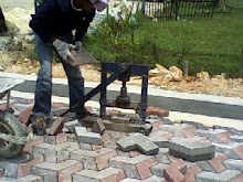
2.6 FORMWORK
 Formwork being done on a construction site in Taman Waja.
Formwork can be classified into 2 types which is:
· timber formwork
· steel formwork
Normally for standard construction in Malaysia, timber formwork is commonly used. Formworks also act as a temporary structure that supports:
- Its own weight
- The freshly placed concrete
- Construction live loads (material, human, logistic)

Timber formwork used for the construction on 2nd and the 3rd floor.
Possible factors (a):
One of the possible factors that lead to the defect on formwork is due to inadequate bracing. This is how it happens:
- Inadequate cross bracing and horizontal bracing of shores is one of the most frequently involved in formwork accidents and failure factors.
- Generally this happen because some unexpected event for example the workers failed to brace the timber together correctly which causes one of the member to fail, then others become overloaded or misaligned and the entire formwork structure collapses
Suggestions on preventing/maintenance:
Among the precautions that can be taken to ensure that the formwork function as it supposes to be is the formwork must be inspected before the concrete is poured. This is to check whether the bracing between the members is correct.
Possible factors (b):
The other reason is that the condition of the timber plays a role as well. This is how it affects the formwork:
- The condition of the timber is very important in formwork. This is because it could affect the concretes quality and strength.
- This happen because the timber is too dry, it will absorb the moisture from wet concrete that had just being poured which could weaken the resultant concrete member.
- Timber with high moisture content (more than 20% moisture content), wet concrete will shrink & cup leading to open joints and leakage of grout.
- The timber also cannot be re-used for a long time because it has limited count of re-use. It can only be re-used 5 or 6 times only.
Suggestions on preventing/maintenance:
- When purchasing timbers for construction work, buy the correct required specification of the timber that is suitable for the construction work.
- Place the unused or extra timbers in a closed area. This is to prevent from exposing to weathering that can cause the defect to the timbers.
2.7 CONSTRUCTION JOINTS
Possible factors:
(a) Slab-column connections:

A popular form of concrete building construction uses a flat concrete slab (without beams) as the floor system. This system is very simple to construct, and is efficient in that it requires the minimum building height for a given number of stories. Unfortunately, earthquake experience has proved that this form of construction is vulnerable to failure in which the thin concrete slab fractures around the supporting columns and drops downward, leading potentially to a complete progressive collapse of a building as one floor cascades down onto the floors below. Even in Malaysia, if the stated method of construction is done in a location where there is loads of heavy transportation passing by daily, the vibration caused would result in such structural failure.
(b) Beam-column Connections:

A final area where better information is needed for concrete building performance is the connection between floor beams and columns. Beam-column connections make the building rigid against the side sway of the building under heavy loading. An example of beam-column joint defect can be seen in the photo in Section 2.3: Column.
Suggestions on preventing/maintenance:
Tie bars are used in construction works mainly to make joints or connections between parts of buildings; beam-column connections or column-slab connections. Therefore, the tie bars are more concerned in construction joints. These are some of the useful recommendations:
- Ensuring that the bars used are appropriate to the loadings bear by the joints, or the numbers of bars used.
- It is important to check that anti-corrosive sleeves are provided in the correct position as they serve as a physical separation to prevent future corrosion of the tie bars.
- Tie bars should be securely fixed in position through openings at the side forms before concreting.
Important Note: Construction joints should be avoided wherever possible. Although a construction joint aims at bonding the new concrete to the hardened concrete in such a manner that the concrete appears to be monolithic and homogeneous across the joint, in practice it is very difficult to obtain full adhesion, with the result that there is usually a plane of weakness at construction joints.
 Tie-bar
2.8 SCAFFOLDING
Scaffolding is usually a modular system of metal pipes (termed tubes in Britain), although it can be made out of other materials. Bamboo is still used frequently in Asia.

Possible factors:
These are the possibilities that might cause the defect of the scaffolding:
· Deformation of material - usually due to reusing a broken scaffold in order to reduce construction cost. Extent of the damage is usually rustiness or crooked scaffold.
· Insufficient component – could be caused by either the workers’ carelessness during construction or due to leakage of coupler during construction of tube cylinder steel scaffolding.
· Overloading – this is the most common failure which eventually results in the deformation of scaffolding materials. Overloading is most probably caused by either miscalculation of the construction engineer or due to workers’ negligence in storing their working equipments on the platform which causes the scaffold to bear additional load beyond its original limit.
· Weather – strong winds, lengthy rain, and extreme hot weather may alter the materials in the scaffold and eventually weaken it.
· Soil condition – insufficient soil load bearing capacity causes uneven settlement which might destabilize the scaffolding structure.
· Insufficient wall ties and sharing
Suggestions on preventing/maintenance:
- Good foundations are essential.
- Often scaffold frameworks will require more than simple base plates to safely carry and spread the load.
- Scaffolding can be used without base plates on concrete or similar hard surfaces, although base plates are always recommended. For surfaces like pavements or tarmac base plates are necessary.
- A working platform requires certain other elements to be safe. They must be close-boarded, have double guard rails and toe and stop boards.
- Safe and secure access must be provided.
As for the purposes of the design of scaffolding:
For softer or more doubtful surfaces sole boards must be used, beneath a single standard a sole board should be at least 1,000 cm² with no dimension less than 220 mm, the thickness must be at least 35 mm. For heavier duty scaffold much more substantial baulks set in concrete can be required. On uneven ground steps must be cut for the base plates, a minimum step size of around 450 mm is recommended.
2.9 TYPES OF MACHINERY AND THEIR OPERATION
These are the types of machinery commonly used in the construction site:
2.9.1 Loader

A loader is also known as a front loader or a wheel loader which is a type of tractor. It is has a front mounted square wide bucket connected to the end of two booms (arms) to scoop up loose material from the ground, such as dirt, sand or gravel, and move it from one place to another without pushing the material across the ground. A loader is commonly used to move a stockpiled material from ground level and deposit it into an awaiting dump truck or into an open trench excavation.
2.9.2 Tractor

An excavator is an engineering vehicle consisting of an articulated arm (boom, stick), backfill blade, an undercarriage and house. The below are the descriptions for the parts of the tractor;
- Articulated arm – The primary purpose of articulated arm is for offset digging around obstacles or along foundations, walls or forms. A secondary use is for cycling in areas too narrow for cab rotation. Articulated arm is one of the major advantages of a compact excavator over other excavation equipment.
- Backfill blade – The backfill blade is used for grading, levelling, backfilling, trenching, and general dozer work. It is the same function as a bulldozer.
- House – The house structure is the main component in excavator which contains the operator's compartment, engine compartment, hydraulic pump and distribution components. The house structure is attached to the top of the undercarriage. The house is actually a rotating platform which is able to rotate upon the undercarriage without limit.
- Undercarriage – The undercarriage consists of rubber or steel tracks, drive sprockets, rollers, idlers and associated components/structures. The undercarriage supports the house structure and the workgroup. It is the same concept as tires for cars.
2.9.3 Concrete Mixer

A concrete mixer (also commonly called a cement mixer) is a device that homogeneously combines cement, aggregate such as sand or gravel, and water to form concrete. A typical concrete mixer uses a revolving drum to mix the components. For smaller volume works portable concrete mixers are often used so that the concrete can be made at the construction site, giving the workers ample time to use the concrete before it hardens. An alternative to a machine is mixing concrete or cement by hand.
2.9.4 Skid Loader

A skid loader or skid steer loader is a rigid frame, engine-powered machine with lift arms used to attach a wide variety of labour-saving tools or attachments. A Skid Steer loader can sometimes be used in place of a large excavator by digging a hole from the inside. The skid loader first digs a ramp leading to the edge of the desired excavation. It then uses the ramp to carry material out of the hole. The skid loader reshapes the ramp making it steeper and longer as the excavation deepens. This method is particularly useful for digging under a structure where overhead clearance does not allow for the boom of a large excavator, such as digging a basement under an existing house.
2.9.5 Bulldozer

A bulldozer is a crawler (caterpillar tracked tractor), equipped with a substantial metal plate (known as a blade), and used to push large quantities of soil, sand and rubble. The term "bulldozer" is often used to mean any heavy engineering vehicle.
The front part of the bulldozer is called the blade. The bulldozer blade is a heavy metal plate on the front of the tractor, used to push objects, and shoving sand, soil and debris.
3.0 CONCLUSION
After the completion of study case on the defects of the parts of building, students would be able to identify on what are the factors that affect the defects on any particular part of the building, as well as suggesting on what possible prevention or maintenance methods to contribute in solving the defects. For an example, the defect on the wall of a building due to drying out of timber frame can be repaired by using a more proper or suitable method instead of just plastering it [Refer to Section 2.4 “Suggestions on preventing/maintenance]. By having the knowledge on how to do maintenance to the defect parts of building, unnecessary premature cost of repair could be avoided. If an improper method is used, the defect might not be able to be curbed completely, and the durability of the part of building could not be prolonged. Students are also exposed to the types of machinery commonly used in construction sites, as there are important terminologies that need to be studied, and also its function/operation. This is important because an engineer needs to have the knowledge on the operations of machineries so that a proper machine would be use to accomplish a certain task.
It is important to be able not only to diagnose simple defects and instruct repairs, but also to recognize and describe those problems which need expert help and act accordingly. Whenever a defect occurs on any part of a building, the root or the main factors need to be taken into account. There are five possible factors that might lead to building defects, which are the climatic condition of the surroundings, locations of the building, the type of building and the change of use (utility), maintenance approach to the building, and also the age of the building. These factors need to be taken care of in order for an engineer to identify which solution is better used to solve the defects/problem.
Buildings are indeed very important, especially in a country’s development. As time passes by, the durability of a building will wear out, and finally, defects will occur on the building. Therefore, the durability of the building comes in as an issue, which as the building has a better durability; unnecessary premature maintenance can be avoided. Without a proper design and construction of foundation, problems such as cracking, settlement of building may occur and even to the extent, the whole building may collapse within its design life. Once again, a building is designed to support the load applied to it safely. From the roof of the building to the substructure or the foundation building has to be concerned about its durability and design.